
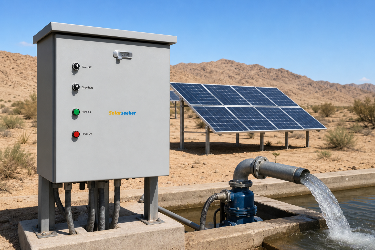
Field engineering breakdown for EPC contractors, irrigation designers, and pump distributors specifying solar pumping drives and outdoor control cabinets.
Direct Answer: What Each Stage Does in an MPPT vs VFD Solar Pump System
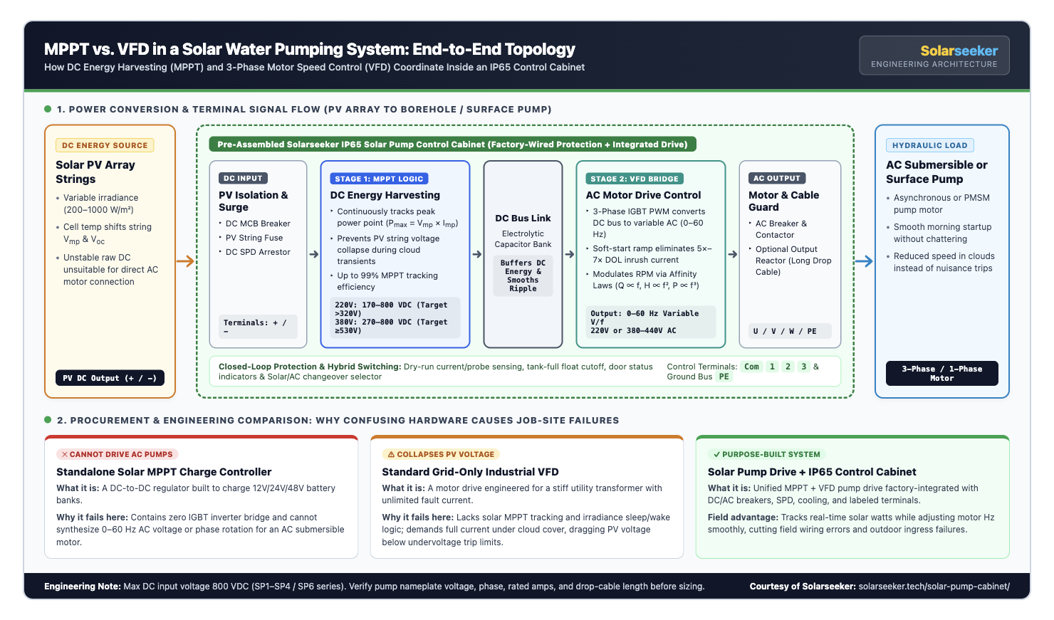
In an MPPT vs VFD solar pump comparison, MPPT and VFD are not competing products—they are two sequential power-electronic stages working together inside a solar pump drive and control cabinet. MPPT (Maximum Power Point Tracking) regulates the DC input side to extract maximum watts from changing sunlight without collapsing array voltage. Meanwhile, the VFD (Variable Frequency Drive) regulates the AC output side, converting buffered DC bus power into variable-frequency three-phase or single-phase AC (0–60 Hz) to soft-start the motor and match pump speed to real-time solar power.
Why Quotations Go Wrong When Buyers Treat MPPT and VFD as Interchangeable
On project tender sheets and distributor RFQs, suppliers frequently throw around labels like “MPPT controller,” “solar VFD,” and “pump inverter” as if they mean the exact same hardware. On the job site, confusing those functions causes two expensive equipment mismatches.
Mistake 1: Ordering a standalone solar MPPT charge controller for an AC borehole pump. A standard solar MPPT charge controller is a DC-to-DC regulator built to charge 12V, 24V, or 48V battery banks. It has no three-phase IGBT inverter bridge, cannot synthesize 0–60 Hz alternating current, and cannot turn an AC submersible or surface centrifugal motor.
Mistake 2: Wiring solar PV strings directly into a standard factory grid VFD. Industrial motor VFDs assume a stiff utility transformer capable of supplying unlimited startup current. When cloud cover drops panel current, a grid VFD still demands full torque, drags the PV string below its minimum DC bus threshold, and locks into repeated undervoltage trips instead of slowing the pump down smoothly.
If your team needs a broader primer on how the drive itself bridges solar arrays and AC motors before diving into subsystem electronics, review our foundational guide on what a solar pump inverter is and how it works.
Stage 1: What MPPT Does on the Solar DC Input Side
Solar panels are current-limited DC generators, not constant-voltage supplies. Throughout a single irrigation day, module irradiance swings between 200 W/m² in early morning haze and 1,000 W/m² at solar noon, while cell temperatures climb from 20°C to 65°C under direct sun.
Higher cell temperatures push array operating voltage (Vmp) down by roughly 0.30% to 0.40% per degree Celsius above 25°C. At the same time, passing clouds cut array current (Imp) within seconds. Without active input tracking, drawing slightly too much current pulls the PV string off its power peak and collapses DC voltage.
The MPPT algorithm inside a Solarseeker solar water pump inverter samples DC input voltage and current hundreds of times per second. It continuously adjusts the effective input impedance so the array stays pinned to its real-time maximum power point:
Pmax(t) = Vmp(t) × Imp(t) | Tracking Efficiency: Up to 99%
PV String Voltage Windows That Keep MPPT in Control
MPPT software can only harvest power when the PV string is wired inside the drive’s verified DC input window. String voltage that sits too low keeps the system asleep all morning; string open-circuit voltage (Voc) that exceeds the 800 VDC ceiling on frosty mornings risks catastrophic capacitor and IGBT damage.
| Pump System Class | PV Array Power Sizing Rule | Verified MPPT DC Window | Recommended Array Vmp Target | Absolute Max Voc Limit |
|---|---|---|---|---|
| 220V Single-Phase AC Pump | PV Array Power ≥ Pump Rated kW × 2.0 | 170–800 VDC | Around 320V DC (over 320V) | 800 VDC |
| 380V Three-Phase AC Pump | PV Array Power ≥ Pump Rated kW × 1.3 to 1.5 | 270–800 VDC | Around 530V–540V DC | 800 VDC |
Notice what MPPT does not do: MPPT never touches phase rotation, motor slip, starting torque, or cable wave reflections. Its job ends at the internal DC bus capacitor bank, where harvested solar energy is buffered for the motor drive stage.
Stage 2: What the VFD Does on the AC Pump Motor Side
Once the MPPT controller stabilizes energy onto the DC bus link, the Variable Frequency Drive stage takes command of the mechanical water pump. Using high-speed Insulated Gate Bipolar Transistors (IGBTs) and Pulse-Width Modulation (PWM), the VFD converts buffered DC voltage into a clean, three-phase or single-phase variable-frequency AC waveform from 0 Hz to 60 Hz.
1. Eliminating 5× to 7× Inrush Current During Borehole Startup
Starting a deep-well submersible motor across the line demands five to seven times its rated full-load current. A solar array has zero surge capacity beyond its short-circuit current (Isc), which is barely 6% to 8% higher than normal operating current. The VFD solves this by ramping frequency smoothly from 0 Hz upward along a controlled V/f curve, lifting the water column gently without stalling the array.
2. Matching Pump Affinity Laws to Cloud Transients
Centrifugal and submersible turbine pumps obey the hydraulic Pump Affinity Laws, where shaft power scales with the cube of rotational speed (and electrical frequency f):
- Flow Rate (Q): Q2 / Q1 = f2 / f1 (linear relationship with frequency).
- Total Dynamic Head (H): H2 / H1 = (f2 / f1)² (square relationship—critical for static well lift).
- Shaft Power Demand (P): P2 / P1 = (f2 / f1)³ (cubic relationship with frequency).
In the field, that cubic relationship is why a well-tuned MPPT vs VFD solar pump control loop delivers far more daily cubic meters of water than fixed-speed setups. If afternoon cloud cover cuts solar array power by nearly half, the VFD only needs to trim motor frequency from 50 Hz down to roughly 40 Hz ((40/50)³ = 0.512, or 51.2% shaft power).
Provided 40 Hz still clears the borehole’s static water head and maintains the motor manufacturer’s minimum cooling flow velocity (typically 25 Hz to 30 Hz minimum frequency clamp), the pump keeps delivering water instead of shutting down.
Side-by-Side Comparison: MPPT Stage vs. VFD Stage in Solar Pumping
When preparing technical submittals or training regional installation crews on an MPPT vs VFD solar pump architecture, use the engineering matrix below to separate input-side harvesting responsibilities from output-side motor protection.
| Engineering Dimension | MPPT Stage (DC Input Side) | VFD Stage (AC Motor Output Side) |
|---|---|---|
| Primary Electrical Domain | Variable PV DC input (170–800 VDC or 270–800 VDC) | Synthesized variable-voltage, variable-frequency AC (0–60 Hz) |
| Core Control Objective | Track real-time Pmax = Vmp × Imp as irradiance and cell heat shift | Regulate motor RPM, V/f torque ratio, soft-start ramp, and phase balance |
| Key Hardware Elements | Voltage/current Hall sensors, DC boost/bus regulation, MPPT DSP loop | DC bus capacitor bank, 3-phase IGBT bridge, gate drivers, current CTs |
| Cabinet Protection Pairing | DC MCB breaker, PV string fuses, Type II DC surge protection device (SPD) | AC breaker, magnetic contactor, grounding bus, optional AC output reactor |
| Typical Fault Codes Prevented | PV undervoltage sleep loops, morning startup chattering, DC bus collapse | Locked-rotor overcurrent, dry-run cavitation, phase loss, thermal overload |
| Commissioning Checks | Verify string Voc < 800 VDC and loaded Vmp at target (~320V or ~540V) | Set motor nameplate kW, voltage, amps, min frequency (25–30 Hz), and rotation |
Wiring & Cabinet Topology: Why Field Projects Mount Both Inside an IP65 Control Cabinet
Understanding how MPPT and VFD interact inside the drive is only half of field reliability. Most standard solar pump inverters (such as IP20 chassis platforms) are open-ventilation industrial electronics designed to sit inside a protected electrical enclosure, not bolted bare onto a dusty irrigation post.
When installers piece together loose plastic combiner boxes, uncoordinated breakers, and bare drives at a remote wellhead, wiring mistakes multiply fast. Loose DC lugs overheat under midday current, unshielded motor cables trigger nuisance ground faults, and fine sand or monsoon rain destroys cooling fans within a single dry season.
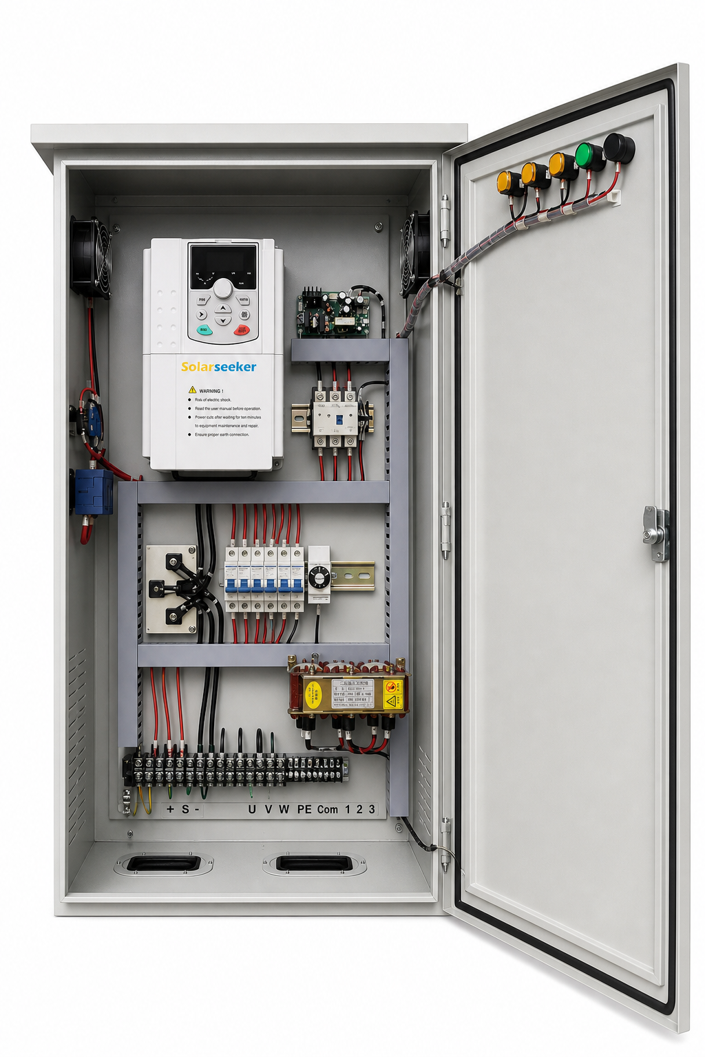
Ordering a pre-assembled Solarseeker IP65 Solar Pump Control Cabinet organizes both the MPPT DC path and the VFD AC motor path onto one factory-tested backplate compliant with IEC 60529 and IEC 61800 enclosure and drive engineering practices:
- Dedicated PV DC Input Zone (
+ / -): Pre-wired DC circuit breakers, string fuses, and surge arrestors isolate the solar array safely during maintenance before power reaches the MPPT input stage. - Clean VFD Motor & Reactor Zone (
U / V / W / PE): Heavy-duty terminal blocks, AC contactors, and optional AC output reactors protect deep-well submersible motor windings when drop-cable runs exceed 50–100 meters. - External Door Operation & Hybrid Switching: Front-door Power On, Running, Stop–Start, and Solar–AC selector switches let farm operators switch between solar array power and backup AC grid/generator supply without opening live high-voltage doors.
- Sensor & Float Control Rail (
Com / 1 / 2 / 3): Labeled low-voltage terminals simplify dry-run well probe and elevated storage tank float wiring so crews finish commissioning in hours instead of days.
This factory-integrated cabinet approach becomes especially critical on high-power commercial irrigation schemes where thermal management, high-current busbars, and clean wireways determine multi-year uptime—such as the configuration discipline proven in our Paraguay 200kW solar irrigation installation.
Electrical Safety Note: Solar pump cabinets combine lethal high-voltage PV DC strings (up to 800 VDC) and three-phase AC motor circuits. Always use qualified electricians, follow local electrical codes, verify PE grounding continuity, and wait for DC bus discharge before servicing terminals.
FAQ: MPPT vs VFD Solar Pump Selection
Can a standalone MPPT solar charge controller run an AC water pump?
No. A standalone MPPT charge controller outputs regulated DC voltage to charge batteries and cannot produce three-phase or single-phase alternating current. Driving an AC submersible or surface pump directly from solar panels requires an integrated solar pump inverter or control cabinet containing both MPPT DC tracking and a VFD AC output bridge.
Can I wire solar panels directly into a standard industrial VFD without MPPT?
In practical field conditions, no. Standard grid VFDs lack dynamic MPPT impedance tracking and solar sleep/wake logic. As soon as morning sun is weak or a cloud passes, the grid VFD pulls excessive current, collapses PV string voltage, and faults out repeatedly on DC bus undervoltage.
When should an EPC or distributor choose a complete solar pump control cabinet over a bare drive?
Choose a pre-assembled IP65 solar pump control cabinet whenever the equipment is mounted outdoors, exposed to farm dust or rain, requires Solar/AC hybrid changeover switches, needs an output reactor for long borehole cables, or must standardize installer wiring quality across multiple sites.
What to Confirm Before Ordering Your Control Cabinet
Getting the MPPT vs VFD solar pump sizing right on the first shipment comes down to matching both sides of the cabinet—the PV string voltage window on the input and the pump motor amps and cable run on the output—before panels or enclosures are ordered.
Whether you are validating a single pilot wellhead or standardizing OEM cabinet SKUs for regional distribution, send these five project details to our engineering desk:
- Pump Nameplate Photo or Specs: Rated kW/HP, voltage (220V or 380–440V), phase, full-load amperes, and rated Hz.
- Hydraulic Duty & Cable Distance: Static/dynamic head, target daily flow, and motor cable length from cabinet to pump.
- PV Module Data (if already selected): Panel wattage, Vmp, Voc, and available mounting space.
- Cabinet & Hybrid Options: Outdoor IP65 mounting conditions, Solar/AC grid or diesel changeover need, and output reactor requirement.
- Commercial Scope: Single-project EPC package, distributor stocking batch, or custom OEM door labeling.
Submit your pump nameplate and site requirements through the Solarseeker engineering contact page for a matched IP65 control cabinet schematic, datasheet, and quotation check.