
Proper solar pump control cabinet sizing determines whether a 15kW to 75kW (20HP to 100HP) agricultural pumping station delivers reliable water for years or fails during its first heatwave. When commercial growers and irrigation contractors transition medium and high-horsepower pumps to solar power, placing a bare variable-frequency drive under an open shed invites rapid failure. Field reliability requires five coordinated engineering elements: an IP65 double-door enclosure with isolated thermal exhaust channels; Class II 1000V DC surge protection; motor-matched circuit breakers and thermal contactors; a 3% output line reactor to suppress dv/dt voltage spikes on borehole cable runs; and an automatic transfer switch (ATS) to blend daytime solar with nighttime generator or grid power.
Standard industrial solar drives such as the Solarseeker SP4 solar pump inverter carry an IP20 protection rating designed for clean, climate-controlled electrical rooms. Operating these units in dusty, sun-baked agricultural fields across the Middle East, Latin America, and Africa requires housing them inside a dedicated Solarseeker IP65 Solar Pump Control Cabinet. Sizing this enclosure correctly protects critical power electronics from driving rain, sandstorms, and thermal overload.
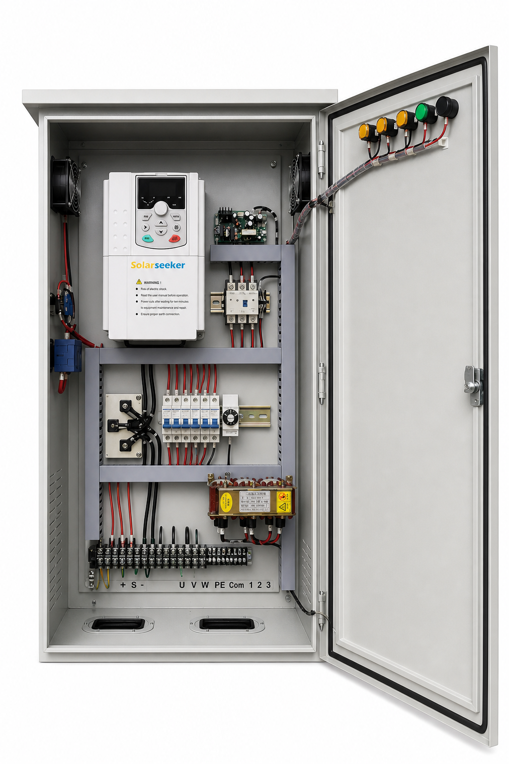
Why 15kW to 75kW Irrigation Pumps Require Engineered Control Enclosures
Small residential pumps below 4kW operate at modest DC voltages and low current levels. In contrast, 15kW to 75kW irrigation systems operate in an entirely different electrical and thermal regime:
- High Direct-Current Bus Potentials: Sizing PV arrays for 380V to 440V three-phase motors requires DC string voltages operating between 540V and 720V DC under load. On chilly mornings before pumping begins, array open-circuit voltage (Voc) can climb toward 800V DC. Opening or closing these circuits under load generates severe electrical arcs that destroy undersized switches.
- Heavy Continuous Thermal Dissipation: Variable frequency drives dissipate roughly 2.5% to 3.0% of their rated throughput as pure heat across their IGBT modules and internal DC link choke. A 45kW drive running at full speed generates over 1,200 watts of heat inside a sealed box. Without dedicated cooling engineering, internal ambient air quickly passes the drive’s 50°C shutdown limit.
- Harsh Farmland Weather Exposure: Agricultural boreholes and river pumping stations stand in open fields. High ambient summer temperatures (often exceeding 45°C in the shade), fine desert silt, driving seasonal rain, and lizard or insect intrusion will destroy exposed electronics. Only pre-engineered enclosures built to IEC 60529 enclosure standards with verified IP65 ingress protection can survive these field conditions.
Sizing Matrix: 15kW to 75kW Solar Pump Control Cabinet Electrical Specs
Selecting matching components for commercial irrigation requires aligning pump shaft power, motor full-load amps (FLA), PV string inputs, surge protective devices (SPD), and output reactors. The table below details recommended engineering ratings across the 15kW to 75kW power spectrum:
| Pump Motor Rating | Full-Load Amps (380V–415V) | Recommended Drive Unit | DC Disconnect Switch (1000V DC) | DC Surge Arrester (Type II SPD) | AC Output Line Reactor (3% Impedance) | Generator / Grid ATS Contactor | Recommended Enclosure Size (H x W x D mm) |
|---|---|---|---|---|---|---|---|
| 15kW (20HP) | 31A–34A | SP4015 (37A rated) | 63A 2-Pole 1000V DC | 1000V DC / In 20kA / Imax 40kA | 35A / 0.40 mH | 40A 3-Pole AC | 800 x 600 x 300 |
| 18.5kW (25HP) | 38A–41A | SP4018 (45A rated) | 63A 2-Pole 1000V DC | 1000V DC / In 20kA / Imax 40kA | 45A / 0.32 mH | 50A 3-Pole AC | 900 x 700 x 350 |
| 22kW (30HP) | 45A–48A | SP4022 (50A rated) | 80A 2-Pole 1000V DC | 1000V DC / In 20kA / Imax 40kA | 55A / 0.26 mH | 65A 3-Pole AC | 1000 x 700 x 350 |
| 30kW (40HP) | 60A–65A | SP4030 (65A rated) | 100A 2-Pole 1000V DC | 1000V DC / In 20kA / Imax 40kA | 75A / 0.19 mH | 80A 3-Pole AC | 1100 x 800 x 400 |
| 37kW (50HP) | 75A–80A | SP4037 (80A rated) | 125A 2-Pole 1000V DC | 1000V DC / In 20kA / Imax 40kA | 90A / 0.16 mH | 100A 3-Pole AC | 1200 x 800 x 400 |
| 45kW (60HP) | 90A–96A | SP4045 (95A rated) | 160A 2-Pole 1000V DC | 1000V DC / In 20kA / Imax 40kA | 110A / 0.13 mH | 125A 3-Pole AC | 1400 x 900 x 450 |
| 55kW (75HP) | 110A–118A | SP4055 (115A rated) | 200A 2-Pole 1000V DC | 1000V DC / In 20kA / Imax 40kA | 130A / 0.11 mH | 160A 3-Pole AC | 1600 x 1000 x 500 |
| 75kW (100HP) | 145A–155A | SP4075 (160A rated) | 250A 2-Pole 1000V DC | 1000V DC / In 20kA / Imax 40kA | 180A / 0.08 mH | 200A 3-Pole AC | 1800 x 1000 x 500 |
Thermal Design: Preventing Drive Overtemperature Trips in 45°C Field Heat
The most frequent complaint in unengineered outdoor solar pumping setups is mid-day shutdown. Under intense summer sunlight, drive internal temperature reaches 80°C and triggers an immediate over-temperature fault (OH2). To maintain full pumping discharge during peak midday sunlight, professional solar pump control cabinet sizing applies three proven thermal management techniques:
- Independent Duct Isolation: The heatsink of an SP4 drive mounts through an internal partition plate, expelling hot heatsink exhaust through an isolated rear or top air channel. This design ensures that outside cooling air flows strictly over the aluminum cooling fins, completely isolating the sensitive internal control circuit boards, microprocessors, and capacitors from dust ingress.
- Forced Industrial Fan Airflow with Washable Filters: Natural convection alone cannot cool a 30kW to 75kW drive inside an enclosure. Enclosures feature dual IP65 ball-bearing cooling fans delivering 350 to 800 CFM of airflow, paired with polyurethane louvers that trap sand particles while allowing hot air to escape freely.
- Double-Wall Radiant Sunshade Canopy: Direct solar radiation hitting a single sheet-metal door easily adds 12°C to 15°C to internal cabinet temperatures. Adding a top sunshade roof and a double-wall door structure with an air buffer blocks radiant solar heating, allowing the system to operate continuously even when ambient field air reaches 45°C.
If project site temperatures routinely exceed 45°C, size the drive one step above the pump motor’s nameplate rating (for example, selecting a 45kW drive for a 37kW pump). This provides extra thermal margin and prevents high-heat current derating.
Surge Protection and Grounding Grid Engineering
Large solar arrays spanning hundreds of square meters act as giant antennas for electrostatic lightning surges. Installing proper surge protection devices is mandatory to safeguard both the inverter and the borehole pump motor.
- DC Array Surge Suppression: Mount a Class II (Type 2) DC surge arrester directly after the main DC disconnect switch. Sizing parameters require a continuous operating voltage (Uc) of 1000V DC, a nominal discharge current (In) of at least 20kA (8/20 μs), and a maximum discharge current (Imax) of 40kA.
- AC Utility / Generator Surge Suppression: When connecting standby diesel generators or a seasonal rural grid feed, install a matching 400V Class II AC surge protective device ahead of the transfer contactor.
- Single-Point Grounding Resistance Rule: According to IEC 62305 lightning protection standards, every grounding conductor—including PV panel frames, lightning arresters, enclosure steel frames, and motor cable shields—must bond to a unified equipotential ground busbar. The measured resistance from this busbar to earth must remain below 4 Ohms. Never separate the PV array ground rod from the wellhead ground rod, as potential differences during a nearby lightning strike create fatal ground loops that destroy inverter electronics.
Managing Borehole Cable Runs: dv/dt Spikes and Line Reactors
In deep-well irrigation and large pivot schemes, pump motors rarely sit next to the solar array. Cable runs between the surface control cabinet and a submersible pump frequently reach 100 to 250 meters.
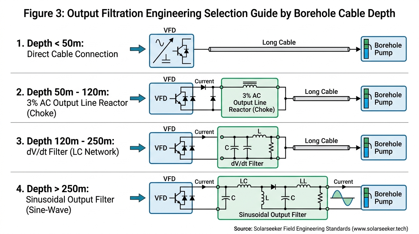
Standard variable frequency drives use high-speed IGBT switching at frequencies between 2kHz and 8kHz. On long motor cables, the fast pulse rise time (high dv/dt, often exceeding 5,000 V/μs) combines with cable distributed capacitance to generate reflected wave amplification. Voltage peaks at the motor terminals can spike to 1,200V to 1,600V, puncturing submersible motor winding insulation and triggering random overcurrent (OC) fault alarms on the drive.
To eliminate this hazard:
- For Cable Lengths Between 50m and 150m: Install a 3% impedance AC output line reactor directly at the cabinet bottom between the drive output terminals (U, V, W) and the motor cable. This reactor rounds off steep PWM voltage edges, dampens peak voltage spikes to safe limits, and reduces high-frequency cable heating.
- For Cable Lengths Exceeding 150m: Specify a dedicated dv/dt filter or sine-wave filter inside the cabinet enclosure. This smooths motor line-to-line voltages into clean sinusoidal curves, matching recommendations from the Food and Agriculture Organization (FAO) irrigation machinery guidelines.
Hybrid Power Switching: Seamless Generator and Grid ATS Integration
Commercial agriculture cannot risk crop stress during critical growing weeks when monsoon clouds or dust storms obscure the sun. Large-scale installations—such as the 185HP center-pivot installation described in our Paraguay 200kW solar irrigation project—require smooth transitions between solar power and secondary AC generation.
A complete solar pump control cabinet sizing layout incorporates an Automatic Transfer Switch (ATS) or mechanically interlocked dual-power contactor set:
- Daytime Solar Priority: The drive draws clean direct-current energy from the photovoltaic array, automatically managing variable speeds to match dynamic sunlight levels.
- Automated Diesel Generator / Grid Transfer: When solar irradiance drops below pumping thresholds or during scheduled nighttime pivot sweeps, the system signals the generator to start. Once generator voltage stabilizes, the ATS switches input power to AC line terminals while maintaining a positive mechanical and electrical interlock to prevent accidental back-feeding into the solar array.
- Controlled Soft Ramp-Down: The control circuit initiates a smooth motor deceleration before transfer switching occurs, avoiding destructive water hammer shocks inside high-pressure irrigation pipelines.
Factory Pre-Assembled Enclosures vs. On-Site Field Assembly
Contractors tackling multi-borehole projects or remote farm developments frequently debate whether to buy loose components or invest in factory-built control cabinets.
Building high-power electrical panels on remote farms presents severe logistical challenges. Field crimping 70mm² to 120mm² copper cables without hydraulic press tools causes loose connections that overheat under load. Missing surge suppressors, incorrectly grounded shields, and unsealed conduit entries leave sensitive VFD electronics vulnerable to moisture and dust.
Ordering a pre-wired Solarseeker IP65 Solar Pump Control Cabinet shifts panel construction into a controlled ISO-certified manufacturing environment. Every enclosure arrives on site fully wired, high-voltage insulation tested, and fitted with industrial disconnects, terminal blocks, cooling fans, and surge protection. On-site installation time drops from two full days down to two hours: technicians simply mount the enclosure onto its concrete pad or steel rack, connect the DC array strings, attach the pump motor leads, and connect the earth rod.
Sizing Checklist for Your Irrigation Project
Before requesting a customized enclosure quotation, assemble four key site specifications to ensure exact component matching:
- Pump Nameplate Data: Motor rated power (kW or HP), full-load operating current (FLA), rated frequency (50Hz or 60Hz), and operating voltage (380V, 400V, 440V, or 480V).
- Submersible Cable Length: Total distance from the control cabinet to the pump motor terminals, noting whether cable is screened or unarmored.
- Power Source Configuration: Pure off-grid solar only, or hybrid solar with standby diesel generator / rural utility grid switching.
- Local Climate Conditions: Peak summer ambient temperature, elevation above sea level, and exposure to blowing sand or maritime humidity.
Whether you are testing an initial pilot borehole or specifying equipment for a regional irrigation tender, submit your water pumping specifications through the Solarseeker Engineering Contact Page to receive a tailored control cabinet schematic, sizing calculation, and factory direct quotation.
About the Author

Andy (known professionally as Solar Pumping System Specialist Andy) is the Founder and Chief Application Engineer at Solarseeker. With extensive field-commissioning experience across deep-well extraction, commercial irrigation, and municipal water schemes, he is dedicated to building simpler, reliable solar water pump solutions for real field conditions. His technical work focuses on off-grid MPPT drive dynamics, high-ambient thermal derating, and outdoor pre-assembled control enclosure engineering.
For technical inquiries, complete cabinet schematics, and engineering guides, visit: https://solarseeker.tech/solar-pump-cabinet/