
A wiring diagram can look simple on paper and still fail on site. The problem is usually not the drawing. It is the missing nameplate check, wrong phase assumption, poor protection layout, or a PV string voltage that does not match the inverter.
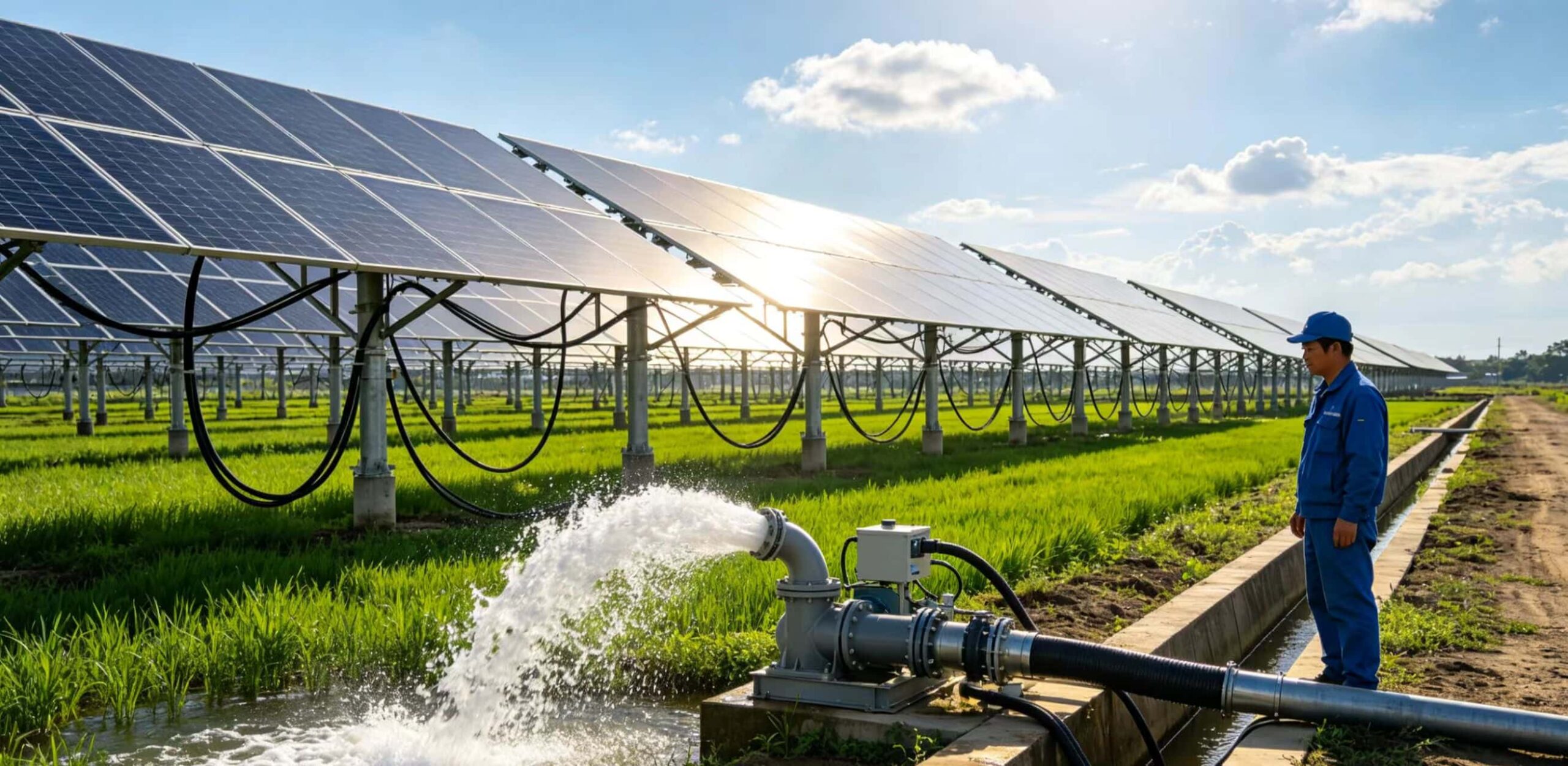
A solar pump inverter wiring plan has four main zones: PV array input, inverter power terminals, AC pump output, and protection/control wiring. A 220V AC pump and a 380V AC pump need different inverter models and different DC voltage targets. For wiring work, follow the inverter manual, local electrical codes, and use qualified electricians.
This article explains the wiring logic, not a live installation procedure.
Start With the Pump Nameplate
Before looking at any wiring diagram, check the pump nameplate.
| Nameplate item | Why it matters |
|---|---|
| Rated voltage | Decides whether the system needs a 220V or 380V inverter output. |
| Phase | Confirms single-phase or three-phase motor type. |
| Rated current | Helps check inverter capacity and protection design. |
| Rated power | Helps size inverter and PV array. |
| Frequency | Confirms 50Hz or 60Hz operation. |
| Motor cable distance | Affects voltage drop and cable selection. |
Do not assume the pump type from the project title. A “220V pump” may be single-phase in one market and a different motor type in another. Use the nameplate.
Basic Wiring Logic
Most solar pump inverter systems follow this high-level flow:
PV array -> DC protection -> Solar pump inverter -> AC pump motor
                       |
                 Control signals
In a real cabinet, the details may include DC isolator, surge protection, AC output protection, water level sensors, float switches, pressure switches, grounding, and communication wiring. The exact terminal labels depend on the inverter model.
For that reason, never copy terminal names from a random online diagram. Use the product manual for the exact model.
220V AC Pump Wiring Logic
A 220V AC pump system is common in smaller irrigation, domestic water supply, and light agricultural jobs. The system may use a 220V single-phase pump, depending on the local market and pump design.
For Solarseeker selection, smaller 220V single-phase pump systems often point toward Solarseeker SP1. The main category path is the Solarseeker solar water pump inverter page.
For PV design, do not only count watts. A 220V single-phase pump inverter often needs around 320V DC Vmp. The PV array also usually needs at least 2 times the pump rated power.
| 220V pump wiring area | What to confirm |
|---|---|
| PV input | String Vmp and Voc are inside the inverter range. |
| DC protection | Isolator, fusing, and surge protection match the DC side. |
| Inverter output | Output voltage and phase match the pump. |
| Motor cable | Cable size fits current and distance. |
| Sensors | Dry-run, tank level, or well level signals match manual logic. |
| Grounding | Grounding follows local electrical code. |
If the PV voltage is too low, the pump may start late or run weakly. If it is too high, the inverter may trip or face component stress.
380V AC Pump Wiring Logic
A 380V three-phase AC pump is common in deep wells, larger irrigation systems, and higher-power farm projects. These systems usually use a three-phase solar pump inverter.
For many 380V three-phase jobs, Solarseeker SP4 is the natural product path. It is often used for larger pump applications where output phase and voltage must match the motor.
A 380V three-phase solar pump inverter often needs around 540V DC Vmp. PV power planning usually starts at 1.3 to 1.5 times pump rated power.
| 380V pump wiring area | What to confirm |
|---|---|
| PV input | Series string reaches the working Vmp without exceeding cold-weather Voc limit. |
| Inverter model | Output supports 380V three-phase pump load. |
| Motor output | U/V/W output sequence is checked during commissioning. |
| Protection | DC and AC protection devices are rated for the site. |
| Cable run | Long pump cables are checked for voltage drop and heating. |
| Control inputs | Float, dry-run, and pressure signals match the project logic. |
The higher DC voltage makes string planning more important. A project can have enough panel watts and still fail if the series voltage is wrong.
Wiring Diagram Planning Table
Use this table before drawing the final cabinet layout.
| System area | 220V AC pump project | 380V AC pump project |
|---|---|---|
| Main risk | Low PV headroom and high current stress | Wrong DC voltage window or phase mismatch |
| PV power start | Pump power x 2.0 or more | Pump power x 1.3 to 1.5 |
| Useful Vmp target | Around 320V DC Vmp | Around 540V DC Vmp |
| Product path | SP1 for common 220V single-phase systems | SP4 for many 380V three-phase systems |
| Typical application | Smaller irrigation, light farm water | Deep wells, larger irrigation, high-power pumping |
This is not a replacement for the datasheet. It is a planning map.
Control Wiring Is Not the Same as Power Wiring
Many wiring problems come from mixing power wiring and control wiring in the same mental bucket. They are different jobs.
Power wiring carries PV input and pump output current. Control wiring handles signals such as float switch, tank level, pressure switch, start/stop command, or dry-run input. The control side may use low-voltage terminals depending on the inverter model.
Keep these points in mind:
- Do not route weak control wires carelessly beside high-power motor cables.
- Check whether a switch is normally open or normally closed.
- Confirm whether the inverter parameter must be changed after adding a sensor.
- Label every control wire in the cabinet.
- Test the control logic before leaving the site.
A pump that does not start may not have a power problem. Sometimes the float switch logic is wrong. A pump that never stops may have the same issue in the opposite direction.
Hybrid and Backup Power Need Extra Care
Some irrigation sites ask for solar plus grid or generator backup. That can be useful, but it changes the wiring and protection plan.
Do not connect backup power into a solar pump inverter unless the model supports that input mode and the manual explains the method. Backfeeding the wrong terminals can damage equipment and create a safety risk.
For hybrid projects, confirm:
- Whether the inverter supports AC backup input
- Whether switching is manual or automatic
- How grid/generator protection is handled
- Whether grounding remains correct in both modes
- Whether the pump parameters change between power sources
If the project needs hybrid operation, tell the supplier before ordering. It is not a small detail to add at the end.
Protection Points Installers Often Miss
The inverter is only one part of the electrical system. Many field problems come from the parts around it.
- DC isolator not rated for the string voltage
- Surge protection missing in lightning-prone areas
- Loose terminals after transport
- Weak grounding
- Long motor cable without voltage-drop check
- Control wires routed with power cables
- Float switch logic wired opposite to the project need
- Cabinet installed where heat and dust shorten component life
These details affect callbacks. They also affect how distributors handle after-sales support.
Commissioning Checks Before Running the Pump
Before starting the pump, confirm:
- Pump voltage, phase, and current match the inverter output.
- PV string Vmp and cold-weather Voc are inside the inverter input range.
- Grounding and protection devices meet local code.
- Motor cable size fits the rated current and distance.
- Water source and dry-run protection are ready.
- Rotation direction is checked for three-phase pumps.
- Frequency and pump parameters match the project.
For any live wiring, use a trained electrician. A solar pump inverter handles DC and AC power, and both sides can be dangerous.
FAQ
Can I use the same wiring diagram for 220V and 380V pumps?
No. The system logic may look similar, but the inverter model, output voltage, phase, PV voltage target, and protection ratings can be different.
Is a wiring diagram enough for installation?
No. A diagram helps with layout, but the installer still needs the inverter manual, pump nameplate, panel datasheet, local electrical code, and site protection plan.
What causes most wiring-related solar pump failures?
Common causes include wrong pump phase, low PV voltage, poor grounding, loose terminals, missing surge protection, and wrong control-signal logic.
Technical Note Before Installation
A good wiring diagram starts with the pump nameplate and inverter datasheet. It does not start with a copied picture from the internet.
If you are preparing a 220V or 380V pump project, send the pump nameplate, panel datasheet, cable distance, and control requirements. Solarseeker can help check the voltage window and recommend the correct inverter path before wiring begins.